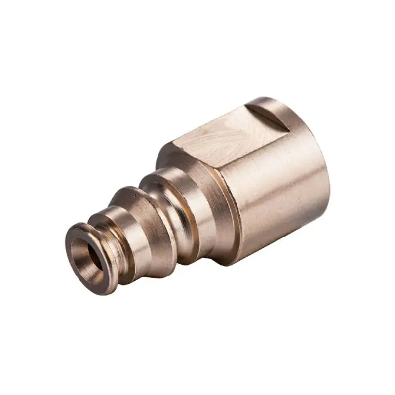
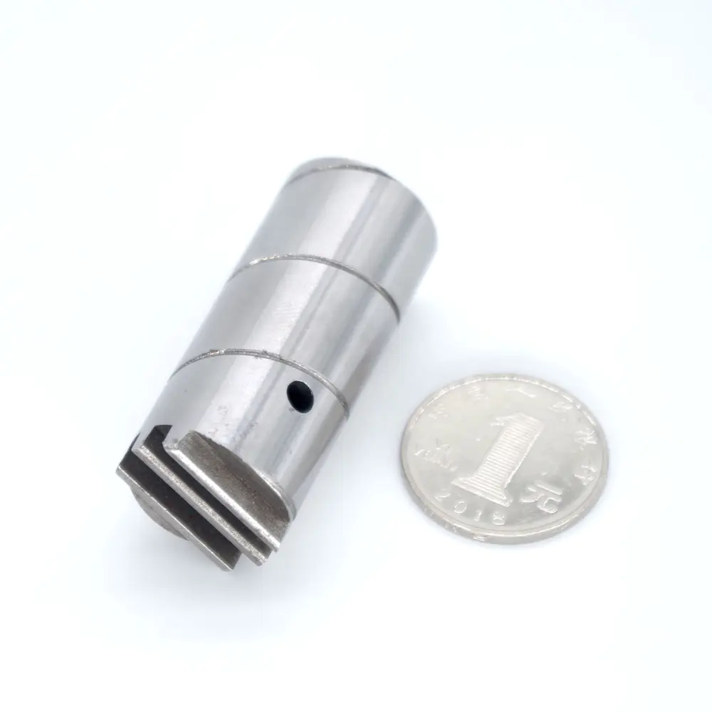
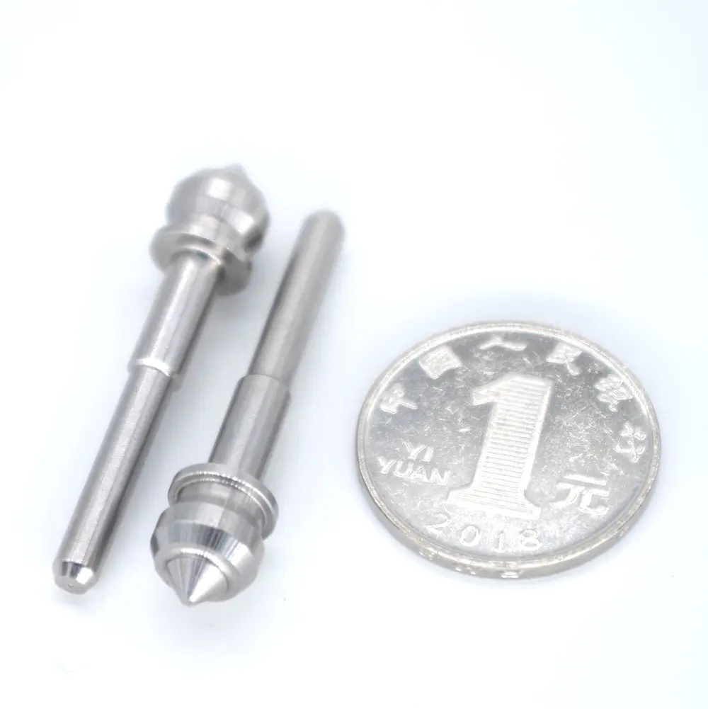
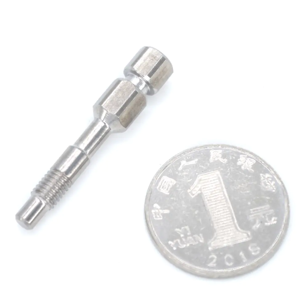
So, you have a CNC laser cutter, but you want a CNC grinder? Problem solved. This project is a small CNC factory that can be assembled from the store. Buy and laser In the absence of a machine tool, cut the parts for about $800. ( It would be helpful if you could go to a shop with chop saw and drill press, but you can get through it with a hacksaw and a wrench. ) It is about 4 \"x 6\" x 1 as shown in the figure. 5 \"working volume, but can be easily extended and modified. This is the killer app for making custom printed circuit boards. But it can also make plastic and wood mechanical parts ( Including all parts of yourself) , Factory custom aluminum dashboard, make template and make art etching for printingmaking. I have included Adobe Illustrator and Autocad DXF files for custom parts, as well as Arduino sketches for controlling brushless motors. The Steps: (1) Words of expectation and caution (2) Buy parts and find tools (3) Laser cutting of custom parts (4)Assemble the Z- Shaft and spindle (5)Assemble the X-axis carriage (6)Assemble the Y-axis and bed (7) Assembly frame (8)Wire it up (9) Adjusting, adjusting and milling tips (10) You might find software that works with existing technology: openMill is really cool, but it\'s not the first or the best table -- Top Mill outside. We are a huge fan of the mit mtm program ( In particular, works by Jonathan Ward, Ilan Moyer and Nadia Pique) And other factories, which are a huge source of inspiration and ideas, we have shamelessly copied many of them. Shapeoko is another good example, there are a lot of people doing neat diy cnc projects and everyone has their own advantages and disadvantages. Expectation: we focus on making it easy for openMill to provide source code for parts, builds, and modifications -- Even at the expense of design elegance or performance. You will almost certainly see the part of the design you want to change This is the point! We try to make it easy for you to make the changes you want. How will openMill perform? It depends on how you build it and how you use it. If it is well constructed, well lubricated, well aligned, and you maintain a lower supply of materials, you should be able to achieve accuracy. 001\" range. But if you can\'t make sure the frame and track are square and try to grind hard material too fast, then you get the sound of bounce and chatter. More generally, even if it may take you only a few hours to assemble the plant, the project is not really plug-and-play. Machining is difficult, so before you can quickly make useful parts from a properly functioning factory, have a learning curve. You might be trying to run bad G-Code. You may not align the axis well at the first attempt. OpenMill can\'t stop you from doing something wrong ( Including things that will destroy the factory). However, these parts are cheap, which makes it a fun way to learn and experiment. Budget: we also try to keep the low cost and the robustness of the design so you can produce openMill for about $800. But if you make a mistake or break something, you should budget some extra money for duplicate parts. Once it starts working, you will find that you want to experiment with some more terminal factories and some raw materials. We tried to make the upgrade easy. For example, if you want to add an interesting threadscrew and wear- Compensation nut ( Increase the cost of the project by about $200) , These parts have included their mounting holes. Security: openMill is a highspeed super- Sharp rotating cutting tools that automatically move without considering the existence of valuable objects (read: fingers)in its path. It can easily dig a hole in your iPhone, hold its hand and throw a metal shave (or broken bit) Clean through your eyes, or ignite the material with friction. It also has no protective cover or safety interlock. Therefore, respect the possibility of injury and danger, do not let it run unattended, wear safety glasses and stay away from it when the spindle is turned on. If you are under 40, seek adult supervision. I get the parts from the following sources: McMaster-Carr (T- Linear shaft, bearing, fastener, acrylicSDP-SI ( Rigid coupling, timing pulley, rotating shaft)Inventables ( Spiral coupler, stepper motor, Arduino, GRBL shield)Hobby king ( Motor and controller)Digikey (Power supplies)MSC Direct ( Bit and bit) The complete list of parts is attached as a CSV file. You can cut the laser. Cut the parts yourself or send them to the online service. I have good experience with the tools you need: Chop saw with aluminum frame ( Or cut saw and some elbow grease) Drilling machine or vertical mill used to drill out the rotating shaft ( Optional but helpful) Pressure vise- Accessories bushing ( But you can use 1/4- 20 bolts and some wrenches) Philips screwdriver 7/32 crescent wrench soldering iron, electric cut meter ruler now you need to make custom parts from 1/4 \"(6 mm)acrylic. Acrylic is a very good material because it is cheap, laser cutting works well and is very hard. Most of the holes in custom parts are gap holes, so it doesn\'t matter if they come out a little big or a little small. But many of the bushes are pressed. So these holes need the right size. This is tricky because if your laser point is bigger, the focus is not focused, or it\'s just hot, you get a slightly larger hole. I put the media Install holes on separate layers of each file so you can resize them ( Test after cutting-holes) Until you get a good mediafit. ( Make sure the hole center stays in the same place! ) If you send the file out, the size of the hole that is too small will go wrong. Opening them with some sandpaper is much easier than making them smaller. ( However, lining them with epoxy will do so at a critical moment. ) You will notice that the top of the cut hole is usually a little larger than the bottom. This can be used as a wedge to help you install the pressure fit part. All 1/4 thick parts can be cut from two acrylic sheets of 12 \"x 24. White acrylic is easy to buy and looks great, but you can customize the look with transparency or any other color. There are also a small number of 1/8 \"thick parts ( These are captive Teflon nut holders in the \"thin\" layer). These can be easily placed on 6 \"x 6\" paper. If you want to try making parts with different materials ( Medium fiber board, aluminum, delrin)then go for it. But acrylic is good. . . Now you\'re starting to assemble! Let\'s start with Z. axis. (1) Use 4 flange bushing and 2 1- Inch brass sleeves connecting the top and bottom plates of Z-axis. Press the flange bushing into the sleeve using the Tai Tiger clamp and fix the acrylic in place. ( This is a very sturdy press, but it is necessary to keep the joints not stuck together due to milling vibration. ) If you don\'t have the vise, you can use some washers, 1/4-20 bolt, a 1/4- Nuts and wrenches. Don\'t over- Press it or you will break the acrylic fiber. Once the bushing and sleeve are installed on the board, make sure that the 3/8 shaft smoothly slides through each assembly. If not, your bushing may be misplaced. A little more urgent can solve the problem. If you don\'t get a smooth sliding motion, your Z- The axis won\'t move very well, so deal with it first before you get it right. Professional tip: If you are under pressure Not very suitable, cool the interior on ice to shrink it. (2) Now add spindle sleeve. This is clamped with a flange bushing on the top plate, but extends to the bottom plate. Similarly, insert the bushing into the sleeve using the vise. (3) Install the fixed teflon Nut Assembly. (4) Add 1 \"bracket-offs (and the 4- 40 screws that hold them in place). (5) Drill out the axis of rotation. This is optional but very helpful If you drill out the shaft, you can block further on the end mill and drill bit, which will reduce the bending and vibration. But to do that, you need a drill bit and a vise to fix the shaft. Use the No. 29 bit and a lot of cutting fluid. It is also helpful to start drilling with a central drill. (6) Add ball bearings, 1/4 \"axis of rotation, thrust washers, rigid shaft coupler and timing pulley. When you tighten the timing pulley to the shaft, press the pulley to generate a pre-load on the shaft. You should have enough pre-load and the shaft cannot slide up and down through the bearing, but it should still rotate freely. (7) Install the motor to the lower board using M3 screws, but do not tighten all the way. Then add the timing pulley and belt of 2nd. Now you can stretch the belt by pulling the motor out of the spindle and tightening the M3 screws. Belt does not matter-just snug. You should now be able to turn the spindle shaft by turning the motor. If you feel the resistance will ease on the shaft pre-load or belt tension. This X carraige holds Z- Axis assembly, and allows it to move up and down, also along the X-axis rails. (1) First, press the flange bushing into the track hole, and then clamp the flange bushing by pressing the flange bushing into the 1/2 brass bushing. Again, a 1/4- Bolts can be used as vise to hold these at critical moments. (2) Install the 20mm right angle bracket on the side plate ( With M5 screws and loose nut) 1 NEMA17 stepping motor ( With spiral coupler) To the top plate (with M3 screws). In addition, add the captured Teflon nut assembly to the side plate (4- 40 screws and nuts). All you need is a tefulon nut. But if you\'re smart, you might figure out how to pre-load two of them to reduce the bounce. (3) Install 4 \"rails and Z- Parts on the shaft. Don\'t forget the thrust bearing and the shaft ring! (4) Tighten the side and top with M5 screws and anti-loose nutsPut the plates together But before you tighten them, slide the 3/8 shaft over X-axis bearings. This will ensure that you do not tighten the assembly in a misaligned way. If the bearings on both sides are not lined up, the carriage will not slide smoothly. You may need to canceltighten and re- Tighten the screws that hold the slide frame together until smoothly sliding from both tracks. Also make sure the Z assembly slides smoothly along the vertical guide. This is the key to getting smooth motion- The car will be able to push the poorly arranged compartment along the track, but it will stick and slide, causing a rebound, not a smooth slide. This part is easy, but to ensure alignment, do not tighten everything before the track is placed in the bushing. (1) Press to install the flange bushing into the 1/2 \"sleeve on the bed panel. (2) Install the teflon capture nut on the bed panel. (3) Screw each bed face Plate into 3 \"bracket-offs using 4-40 screws. (4) Pass the 3/8 \"rod through the panel and tighten all the parts. (5) The grinder is made of two layers of 1/4 \"acrylic. Small holes in the bottom layer, designed as 8-32 threads. These are super Useful for getting stuck in the bed, so click on these holes. ( This is a project with a manual faucet -- You will hurt after that. ) Once the holes are tapped, place the bed on the hook at the top of the panel and fix it with acrylic cement or epoxy. The top floor is a scrap plate, there are 8- 32 holes, so 8- 32 screws can reach the threaded holes in the bed. The aluminum T- The slot frame is a bit expensive, but it\'s very easy to modify and redesign Used, it is also quite hard when assembled correctly. (1) First 4- Foot length of frame size. What you want is :[piece lengths]. The Chop saw works well in this regard, but you can do the same by hand with the hack saw. (2) Use the 20mm gasket now (with M3 screws) Assemble the rail bracket and install it to the cut T-slot framing (with M5 screws). ( It turns out that it is much easier before assembling the frame than after assembly. ) You don\'t need to tighten the screws- You want to be able to slide the brackets to align them. Foot boards and rubber feet can also be installed. (3) Now use end-assemble the frame Feeding fasteners and angle brackets. However, when you build it, you will want to install the guide rail, shaft ring and bracket assembly. (4) Once everything is basically put together, you will want to make sure that X-and Y- The components slide smoothly on the track and are perpendicular to each other. If not, loosen the rail brackets and push them slightly before reinstalling. This is a critical phase. Your grinding will only be as good as the smoothness of the trip and the verticality of the rails. Also make sure Z- The track is tilted up instead of forward or backward. (5) Once everything is smooth and straight slide, add the threaded guide rail to the motor using the screw coupler. (6) Install the Arduino to the mounting board using the bracket and end- Install the fasteners on the track. Now is the time to connect things! Pop up the Arduino with the GRBL shield and then :(1) Connect the motor to the GRBL shield. If there are no connectors on your motor, you can bring them directly to the screw head. If they already have a partnerN-Lok connector (or similar) It\'s worth making an adapter on them. (Mate-N- The bare wires of Le Tao. ) Check the GRBL mask documentation to ensure proper wiring. (2) Connect the power adapter to the GRBL shield. Again, it\'s worth making the adapter so you can easily unplug the power from the shield. I used a 2. 1mm barrel connector. (3) Connect the brushless motor to its electronic speed controller (ESC) Use 3 press-plugs. ( Don\'t worry about getting the right lead mapping If we end up powering the motor in the wrong direction of rotation, you just need to replace two of those plugs. )(4) Program the 2nd Arduino using the supplied automatic rotation driver to control ESC. ino sketch. This sketch sends a PWM signal to initialize ESC (Will Doodle) And then slowly increase the throttle to speed up the motor. You can set the rate and maximum speed by changing the variables in the sketch. Don\'t connect the Arduino to your computer (eg. For programming) Also ESC. ESC may overdraw the current from the USB port, hurting your computer or Arduino. After the Arduino programming is complete, disconnect it from the computer and connect it to ESC. On my ESC, the black line changes to \"ground\", the red line on Arduino\'s \"Vin\", the white line on the PWM pin, and pin 10. Once ESC is powered on, Arduino will draw power from ESC. (5) Start ESC by plugging in the power supply. You should hear a few beeps from the motor and then it will start to spin. If your motor starts and then suddenly stops, it may be because you run too fast and the current of the ESC or power supply is too large. Re- Program the Arduino to drive it at a slower speed and try again. To stop the spindle, unplug ESC from the power supply. If you notice that the spindle rotates in the wrong direction, turn everything off, swap the two leads of ESC to the motor, and try again. (6) Start the GRBL shield. Detailed instructions for setting up motor current and configuring GRBL for your design are as follows: you need to provide some information about the rolling mill to the shield, such as the amount of travel generated per step. 200 steps/turnmotors, 20 rev. The/inch screw and 8 times subdivision shield need to be produced 1259. 8 steps to move 1mm. It\'s a big job to learn how to grind, but some special tips for openMill will help you get started. (1) Really make sure the axis moves smoothly and parallel. Use mechanic Square ( Or any other reliable right angle)to make sure. (2) If the spindle has too much vibration and noise when the motor is turned on, try changing the motor speed (up or down) , And check the pre-load on the spindle shaft. If the shaft is clamped too tightly by the pulley, it does not rotate smoothly It\'s too loose to rattle. (3) It is common that the bed surface is not completely flat relative to the tool movement. But you can solve this problem by using a large vertical mill (or part of it)flat. This is especially useful for fine etching, just like a pcb. These tools are cool, but sometimes they go wrong. I always check G- The code they generate in the simulator to make sure they don\'t do anything crazy. Keep in mind that GRBL can\'t always explain all G- The code generated by the CAM program, which also causes problems. Take risks on your own and realize that you may break some tools. Universal G-code Sender -Cross- Platform GRBL compatible software for sending G- Code for the factory. PCBgCode - This eagle ULP produces G- The PCBs of the code that isolate the EagleCAD route. Inkscape -Open- Drawing of source vector graphics. MakerCAM -Free open-source G- Generate code from the uploaded SVG file. OtherPlan - Free CAM software for G-Code generation.