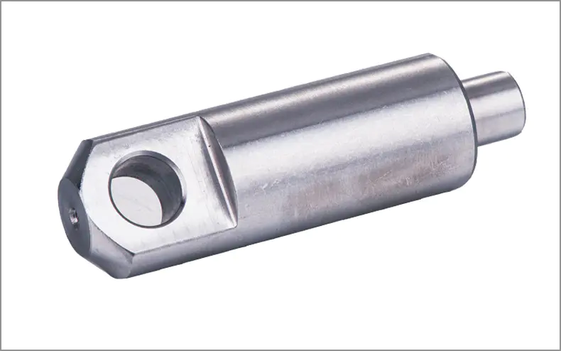
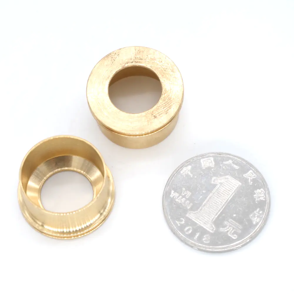
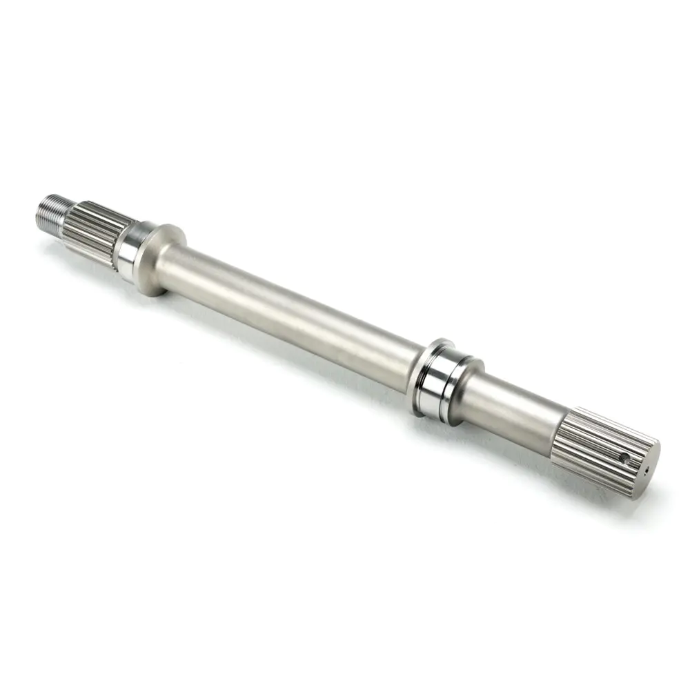
Hello everyone, welcome to my first tutorial! Today I will show you how to design drawing CNC using Digilent Arty board, DC motor and RC servo system as main hardware components. Important: Since I am currently working on this project, I will show you how to build the CNC and how to control it using the Pmod button. In the next update, the Android and Bluetooth sections will also be introduced and explained. Since I started this project, there has been a huge interest in the painting machine, so I am trying to break the routine and implement the abstract portrait drawing technology of reality, the use of 4 watercolor pens- Brush and 1 sponge. The portrait that will be drawn will eventually be sent from the phone via Bluetooth with a special Android app that I created using Android Studio and Android OpenCV Library. The project will end up like this. Currently, only the requirements for controlling the CNC through the button will be displayed. Other parts described throughout the project will be included and explained in the next few weeks. To build it, we will divide the project into three main parts: the mechanical part, the electrical part and the software part. Material of mechanical part :- 3X1 m GT2 timing belt- 4 GT2 pulleys 3X1 m screw bar- 16X8mm inner diameter bearing-16X8mm screws ( Should cooperate with bearing)-70 X 8mm nuts- 9x1 m 90 degree aluminum corner profile (25mm x 25mm)- Wood: 2X58 cm x 5 cm x 2 cm, 1X24 cm x 6 cm x 2 cm. Other materials :- More screws in various sizes-screwdrivers-saw- 3mm and 8mm drill bits Duck antenna and hardware for electrical part :- Art Committee FPGA Development Board-PmodBTN- 2 X Digilent DC motor/gearbox (1:19 ratio)-2 X PmodHB5: H- Bridge Drive with feedback input- 2 x gws servo: s03 txf STD- Single motor installation materials :-1. 5m wire bus- 10 wires from men to women More about the software section :- It took me a long time for this part, so I might skip some details. I will be as clear as possible. 1. Axis slider- Cut the aluminum angle with the specified size (first figure)- Drill 8mm holes in their exact position: first drill a smaller hole in that position (e. g. of 3mm) Then drill the accuracy of 8mm holes- Add bearings, screws and nuts to the sliding angle (fig 1)- Cut 4 blocks of wood (2cm thick) And drill a 8mm hole in its specific position (fig 2)- Cut 8 pieces of wood ( 5mm thick and aprox. 5cm x 2. 5cm)(fig 3)2. Set the main frame- Take 3 sticks and cut by specific size Now install the cutting parts as shown in Figure 4 and Figure 5 Note: cut some 5mm thick wood blocks (aprox. 5cm x 2. 5cm)- They are used in figure 4 and figure 53. Set the intermediate frame- Put a piece of wood ( 24 cm x 6 cm x 2 cm) Make its end as sharp as in figure 2. Arrange it like a hole in figure 7 and use some screws to fix it (fig 6, fig 7) Note: in my project, I mistakenly put one of the sliders in the opposite position. I didn\'t change it in the end because it didn\'t make any difference, but it\'s better to be careful and place it correctly from the start -- Assemble the entire CNC and add 2 planks of the same length as the y-axis. As long as you know how high you want your CNC to be, you can choose any height (fig 8). 4. Increased DC motor and servo system Figures 9 and 11 illustrate the position of the DC motor and the servo system. I also used some Meccano parts for the design drawing 10. If you don\'t, you can improvise in this section. - When the lid of 2 DC is added, the x-axis slider is able to properly fix the belt holder and the y-axis DC motor. A board should also be added (or a cardboard)under the CNC. It looks better, and now CNC will start drawing better in this part of the pen selector. Using duck tape, you should tie your crayons to an unused servo or next to it. Tips: belt does not matter! They should be relaxed, otherwise the system may not work properly. Good job! Now our CNC is ready. Next, we need to connect the electrical CNC parts to the circuit board in some way. Due to the short Digilent 6-pin cable connector, I had to extend the connector with tin welded wires and pins. Figure 12 shows where the Arty board is in my project. From this position I have used the 150 cm wire to connect the y axis DC motor and the servo system. Using the Digilent cable connector, the x-axis DC motor has been directly connected to the board. I suggest you measure the length of your own wires based on where you want your board to stay. Figure 13 shows the connection between the motor and the press plate. Tip: an external power supply is also required for HBridge. The best is 3. 3 V. Because of this, I connect them to the Arty Arduino/Chip Kit \"shield\" connector pins for output 3. 3 V. More tips: it is best to connect all VCC of the motor to external power supply ~ 5 v. The programming part of this project is completely done in a hardware description language, and I prefer to write my own component implementation, although you will find various code examples that control RC servo/DC motors. In order to control these two types of motors, we need to implement PWM (Pulse- Width modulation). If you are not familiar with it, try searching for more information on the Internet. If you would like to learn more, you can also read how the servo system and the DC motor work. Each motor has a different PWM cycle, so in the end we will have two different pwm codes for simplicity. Control the DC motor through the H bridge control. In the H-bridge data sheet, we see that the input enable pin should be connected to the PWM signal with a cycle of 2 KHz. Since the internal clock frequency of the vassal elegance is 100 MHz, in order to obtain the desired clock cycle of 2 KHz, we will divide it into 100 MHz/2 KHz = 50000. So I used a counter from 0 to 49999 and the counter automatically refreshes when it reaches 50000 and forces the PWM output signal \"1\" and the flag \"1 \". For duty cycle, I used another counter and when the flag is \"1\" it starts counting based on the fill factor and when it is done it forces the flag back to \"0 \". The fill factor is stored in the array as a constant in the PWMs architecture. Since we need the DC motor to stop after moving some steps, in which case the PWM signal should be 0, I added another input signal to tell us if the motor should move. If not, we set the output PWM to 0. In this step of the project, the PWM on the DC is a bit irrelevant. The importance of the DC motor encoder and PID control will manifest in the next few weeks when it will be implemented. Currently, the direction of the motor will be set automatically according to the button pressed. We control two DC motors in the same way. In the implementation of the project, only one RC servo needs to be controlled-the up-down servo. The pen selector servo will be displayed next week. The servo system input PWM should have a period of 2 MS. This means the frequency of 50Hz. Like before we did math, we got 2000000 counts. The principle is the same as before, but this time we don\'t care if the PWM signal stays the same ( Actually, we do this, but not the way we care about DC Motors) Because for the servo, a certain factor fills us to a certain extent. The servo will move according to the input from the circuit board switch. It\'s either up or down ( In this position, the pen will draw on paper). The component that binds all the above components together is implemented, called CNC. = NC Code---------------DC motor pwm----------------------- The ROM type is an array (0 to 4)of integer; Constant my_nums: ROM: = (0 => 0, -- 0 DC 1 => 12500 ,-- 25 DC 2 => 25000 ,-- 50DC 3 => 37500 ,-- 75 DC 4 => 50000--100 DC ); Signal pwm _ temp: std _ logic: = \'0 \'; Pwm _ temporary _ cnt signal: integer: = 0; Integer: = 0; signal duty_temp: Signal flag2: std _ logic: = \'0 \'; Signal selector: integer: = 0; Start the process (clk)begin IF(RISING_EDGE(clk)) Then, if the selector = 0, then pwm _ temp